VT-Speedster Instructional Manual


Instructional Manual
REV 2.0
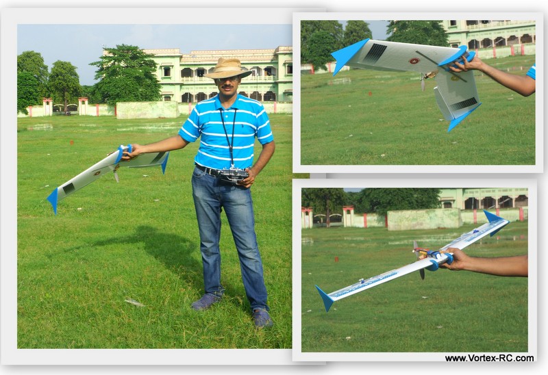
Congratulations on your purchase of the “ Vortex-RC VT-Speedster” / “ Vortex-RC VT-Speedster PRO” . Flying Wings have always been fun to fly. However they require precise design and calculations to get them fly just right. Vortex-RC is proud to introduce the VT-Speedster and the Pro editions. Designed and built to perfection , The Speedsters have ‘just’ the right airfoil, taper, sweep, twist and CoG. Build is super easy and we are sure the Speedsters will be loads and loads of fun to fly with.
Please take time to read through this manual in detail as well as watch our videos that illustrate the build steps. Flying wings need to be built as designed so please follow the measurements as accurately as possible. Unlike traditional airplanes, flying wings fly real bad even if the CoG is off by 10 mm. So please follow instructions as accurately as possible. We recommend that you read several steps ahead and test fit parts without using glue and once you double check everything then only use the adhesive. Our precision laser cutting and CNC hot wire cutting techniques ensures you will need minimal or no modifications to parts for a fit, and that all fits are tight and accurate. If you find any part that does not fit properly, please read the instructions and see pictures again to reorient/align correctly before using any glue.
We have written this manual so that the kit can be built individually as well as by groups of students/builders. Please follow the build in the order as written below.
Additionally we have given 2 check mark places besides each step. 
Check mark the first box when you complete the step. Check mark the second one, after you double check the step, or when doing group builds have your project coordinator inspect and check it for you.
Watch our build videos, now on Youtube.From unboxing to the maiden flight, we have it all on videos for you to see, learn and follow to ensure you get the most out of the Speedsters. Search Vortex-RC on Youtube, or follow the link : http://goo.gl/GMhxgG |
|

Contents
| Document Revision History | – Page 3 |
| What’s in the kit. | – Page 4 |
| What you need in order to complete the kit. | – Page 4 |
| Some basic stuff about materials used, and adhesives | – Page 5 |
| The build ! | – Page 6 |
| Cut out the coro parts | – Page 6 |
| Laminate the wings | – Page 8 |
| Cutting out battery bay and elevons | – Page 11 |
| Bevel and hinge the elevons | – Page 13 |
| Join the wing panels | – Page 15 |
| Join the wing panels for Speedster Pro | – Page 16 |
| Assemble and install motor mount | – Page 18 |
| Install servo and control linkages | – Page 19 |
| Install other electronics | – Page 19 |
| Install winglets and skids | – Page 21 |
| Measurement checks | – Page 21 |
| Go out and enjoy | – Page 22 |
| Appendix A Field packing checklist | – Page 22 |
| Appendix A – Preflight | – Page 22 |
| Appendix B – Trimming Guide | – Page 23 |
Important Measurements/Specifications:Wingspan: Speedster : 990mm Speedster Pro: 1180mm Elevon Dimensions:
Battery Bay cutout dimension (only for VT-Speedster ):From the leading edge : 2cm Control Throws:Measured at Trailing edt on Tip ( where Max deflection occurs ) |
Document Revision History
Rev 1.0 – June 9th 2014
Rev 1.1 – July 23rd 2014
Rev 2.0 – August 6th 2014
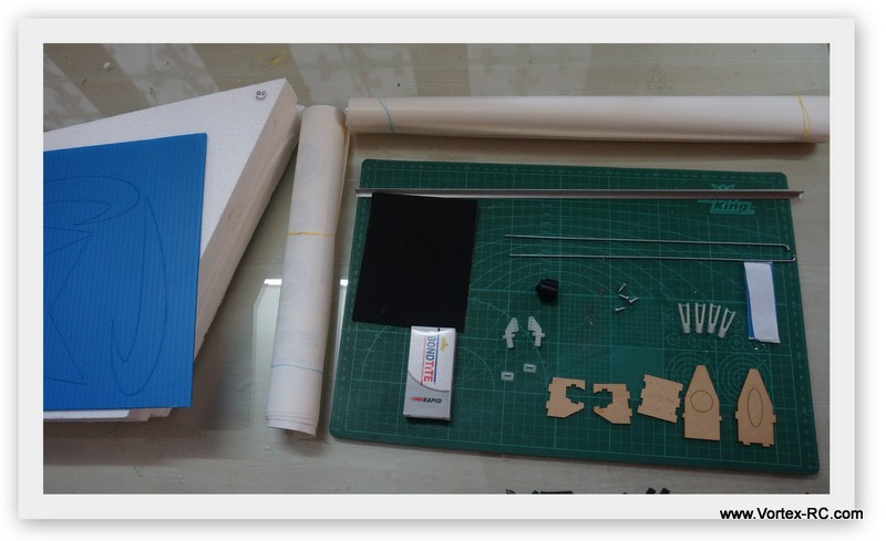
What’s in the kit.
|
|
For Speedster PRO you also get :
|
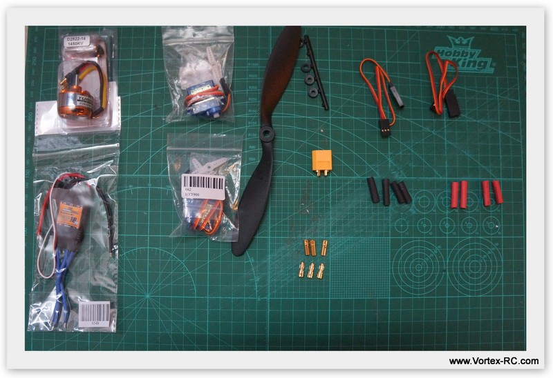
Electronics Package (Optional) includes:
|
|
In order to complete the kit you will need the following
( check mark against each once you collect the items ) :
|
o Screw Driver |
o 90 deg Set Square |
You also need a clear and a flat table/surface or floor to work with. This is very important. Having a flat surface will ensure your build goes straight and true.
You will also need the following to fly :
- 2200/3300 mah 3S Lithium Polymer Battery
- 1 Nos Lithium Polymer Battery Charger.
- 4 Channel or above radio set ( Tx and Rx ) (with Elevon mixing feature)
About EPS Styrofoam
EPS, or Expanded Polystyrene , is commonly known as Thermocol and Styrofoam, is a closed cell rigid and tough foam. EPS foam is available in various densities and we use a high density EPS foam for CNC cutting our wing panels.
EPS foam is perfectly suited for hot wire CNC cutting, as it warps minimally and when cut the material is absorbed in the outer layers of the foam and does not bead, like XPS foam, which is prone to warping and beading.
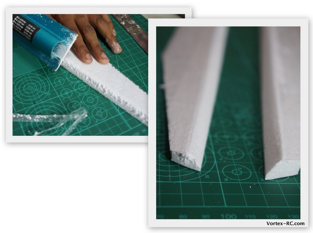
EPS foam melts with CA adhesive, but Epoxy adhesives work great with it. Also, EPS foam can be strengthening by laminating it with clear packing tape.
When laminating, lay out parallel strips of packing tape, overlapping each line with around 2 mm. Lightly iron the tape for better adhesion. Be sure the iron temperature is low enough to not warp out the wing.
We ship the wing panels in their original wing beds. The wing beds not only provide protection during shipping, but also should be used as jigs, when laminating and sparring to reduce the chances of wing warping.
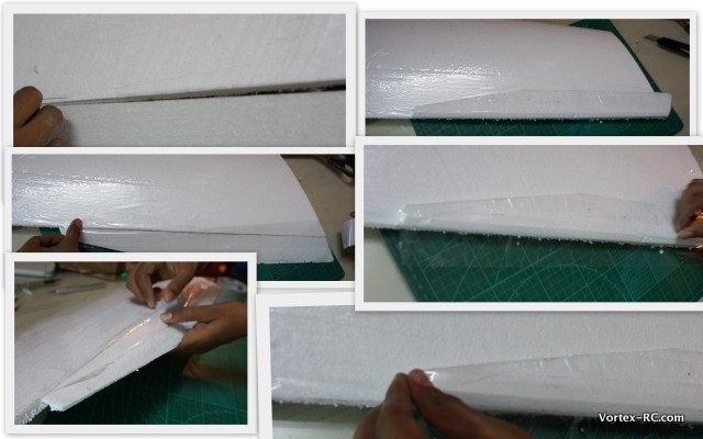
Hinging Technique.
Please follow the hinging technique as described below. If followed properly the resultant hinge would be very strong, yet light and easy to do. Follow the steps as below:
- After lamination, using a straight edge draw a line and cut where you want the control surface to be
- ON the control surface, bevel the underside as illustrated
- Use 2 small pieces of clear packing tape to hold the control surface in place
- Now bend the control surface to 45 degrees and apply a full length of clear packing tape along the joint. Half of the tape would be on the wing and half on the control surface
- Now turn the control surface on its back and use a small tape to hold it in place.
- On the underside put a full length of tape along the hinge joint, as illustrated,
Try to ensure that there is minimal hinge gap and that the control surface is kept as straight as possible,
Lets start the build !
Building the Speedsters is lots of fun and can be done in about 4 hours. Read the manual and understand each step before actually doing it. You may also see our videos that will assist greatly.
|
Note: The Speedster Pro is built using exactly the same way as Speedster. There are some differences only in a few steps and we shall highlight them below as we proceed with the building in these yellow boxes. |
Build Steps:
- Identify the parts and cut out the Coro parts from the sheets.
- Apply Decals and Laminate the wing
- Cut out and the Elevons and the Battery bay
- Bevel and hinge the elevons
- Join the Wing panels
- Assemble and install the motor mount
- Install servos and electronics
- Install the Winglets and the skids
- Final Measurement checks.
- Go Fly !
Step 1: Cut out the Coro parts  15 mins
Cut out the four skid parts and the two winglets from the coro sheets carefully. The 4 skid parts are doubled up to make 2 skids. Note that two skids parts have horizontal flutes and two have vertical flutes. After the parts are cut out, glue one horizontal and one vertical skid to each other using a few drops of CA. Likewise make the second skid. 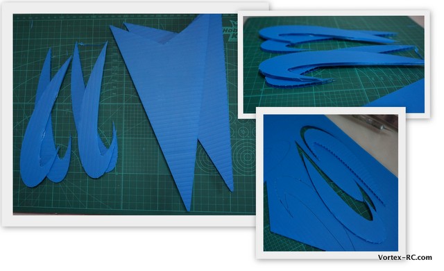
Repeat steps 2,3 4 for each wing panel
Step 2. Laminate the wing 30 mins
Lightly sand the panels using the 320 grit sand paper strip provided. Sanding removes the fine layer of surface foam, which leads to better adhesion of the tape. Sand very lightly so as to not to modify the airfoil . Once sanded, the foam will be smooth to touch.
Cut open the wing beds into top and bottom halves and label them accordingly. Place the wing over the bed during the sanding and laminating process. This ensures that you do not induce a warp in the wings.
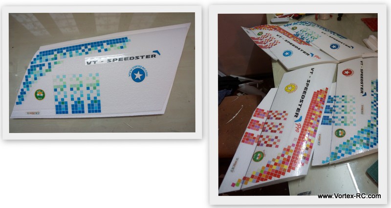
Before Laminating, install the decals, as shown below. The reason why we choose to install the decals first is that the lamination will seal the decals and it adds to the longevity of the decals.
The supplied 2 sheets of lamination material are adequate to cover both the panels. However follow instructions carefully so you do not run short of it.
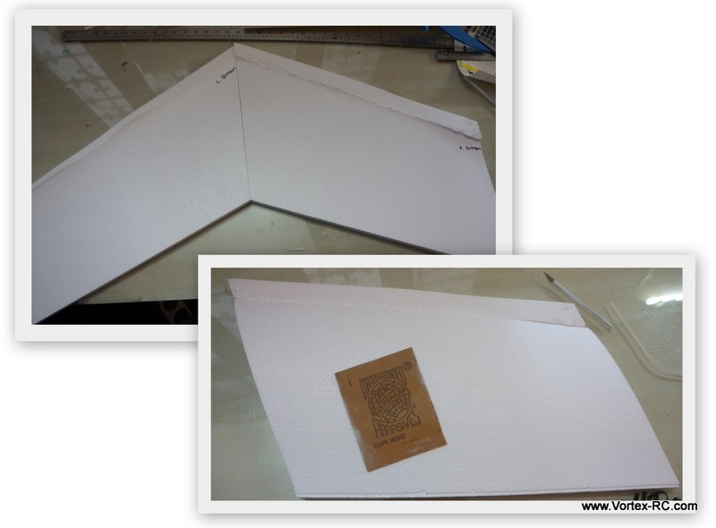
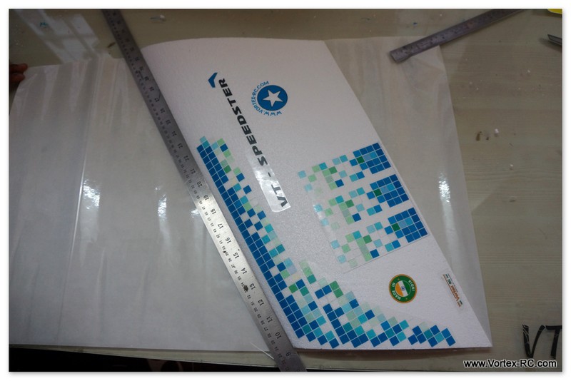
Place the wing over the lamination sheet as shown below aligning the root and tip ends. Accurately cut the lamination film near the leading edge
The remaining material shall be used for the other wing panel top. To cut the bottom wing panel, repeat the above stop with the other lamination sheet. This time keeping the wing upside down.
So you shall have 4 sets of diagonally cut lamination sheets.
Laminate the bottom wing panel first. Place the wing over the top wing bed, upside down, and from the trailing edge laminate till the leading edge. Using a ruler cut the excess off. keep about 5mm of the laminating material excess from the trailing edge.
You can trim off the sides, but do not trim of the trailing edge material yet.
Now invert the panel and put it the right way up on the bottom wing bed. Again laminate from the trailing edge, keeping about 10mm excess material on the trailing edge. Take care to avoid forming any wrinkles. Overlap on the leading edge by about 10mm and using a straight edge, cut the laminating material off.
Be sure to keep the wing panels over the beds to avoid warping.
The trailing edge material will stick from the top and bottom sides and create a seal. Using a straight edge this can now be trimmed out.
Step 3. Cut out the battery bay and the elevons 15 mins
The battery bay is cut out on the root side of both the wing panels. Follow the measurements as noted below and cut out the bay accurately using the knife. The bay is designed to fit a 2200mah 3S.
From the leading edge : 2cm
Bay depth: 1 cm
Bay length: 10.2cm
Bay width: 1.5cm
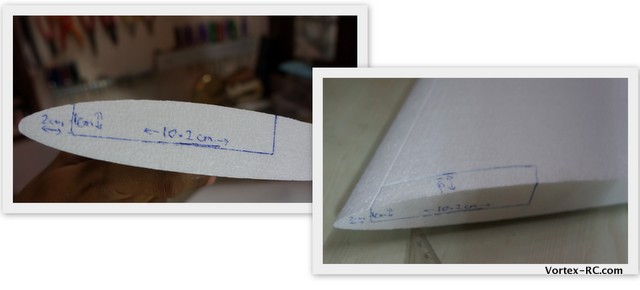
Draw a line with a pen as below and cut out accurately.
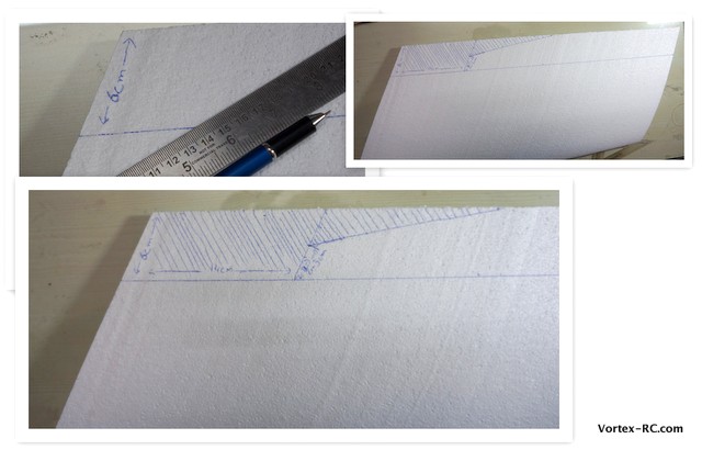
For the Elevons, Draw out lines as noted below:
- 6cm parallel to trailing edge. All the way from tip to root . This will make the elevon.
- 14cm from the root parallel to the root. This cuts of space for the prop
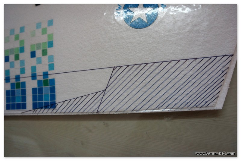
- 3cm from the inside of elevon to the ⅓ point of Elevo (approx 13cm)n. This tapers the elevon and gives the wing better flight characteristics.
For Speedster Pro :
|
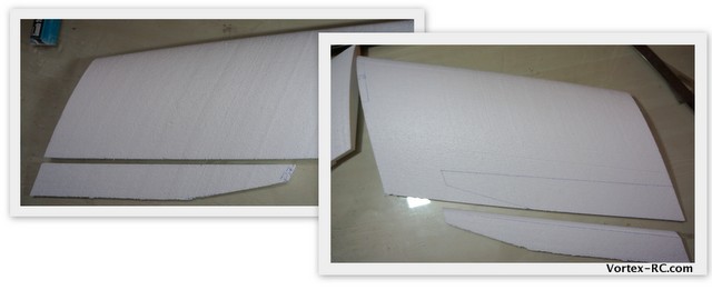
Use a knife with a sharp/new knife to cut out the lines. As illustrated above the area with the parallel lines is scrapped.
Once cut out, use the elevon to trace out the pattern on the other panel and cut out. Its very important to have identical elevons. This step will make you have both elevons in the same size and shape.
OK, so both the Elevons are cut out. Lets bevel them out and hinge them Read all the steps ahead and do this patiently. Good hinging will make your plane really nice to fly . Want me to say this again in Chinese ? IMP: Hinge properly Plane fly good. Lol !
Step 4: Bevel and hinge the elevons 30 mins
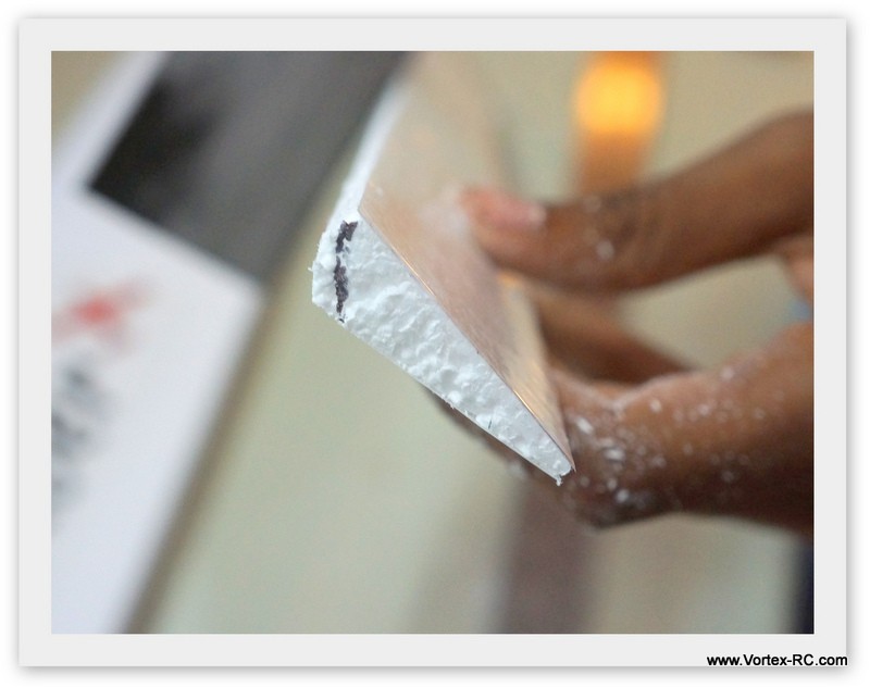
The next step is to bevel the ailerons. Mark a 45 degree line from the top of the elevon on the side as shown. The idea is to bevel the bottom side so that the hinge line will be created on the top edge. Put the elevon back side up draw a line, parallel to the length of the elevon about 1 CM behind the leading edge. Carefully cut out the lamination material from this line. Sand carefully so that the bevel is created uniformly across the length of the elevon .
For Hinging, Follow these 4 steps to create a slop free, tight and reliable hinge joint:
A. Use 3 small pieces of tape to hold the aileron tightly in place and fully deflected in Down position. Make sure the top line is aligned properly
B. While keeping the aileron deflected apply a length of clear tape along the joint.
C. Flip the Aileron the other side, and tape in place using a small piece.
D. Apply some more packing take along the joint from the other side.
Repeat the above steps for the second panel.
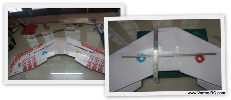
Step 5: Join the wing panels 20 mins
|
The Speedster PRO wing panels are joined differently, scroll down to see the steps to follow for the PRO version |
Working on a flat table, Align the panels together accurately so that both the leading edge and trailing edges match up and the wing lies flat on the table. You may also use the wing beds in this step.
If needed lightly sand the Roots so that the left and right sides mate perfectly. 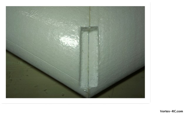
Mix up some 5 Minute epoxy and apply to both sides and glue the left and right panels together. Use packing tape to reinforce the entire center joint. Double check to make sure the wing panels are straight and lie on the flat table.
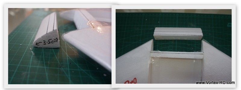
Once the glue is cured, we shall install the spar. The spar is installed on the bottom side of the wing. The supplied T-Spar section is 44Cm. Mark the center point.
Do the following steps very accurately.
- Mark a point on the center joint 18 cm from the leading edge. This has to be on the wing center joint.
- Draw a straight line from here that extends 22cm into each panel. Make sure the line is straight by measuring the ends of the line against the wing’s leading edge.
- Use a knife to cut the Spar slot .
- Enlarge the cut slightly, by sliding the T-Spar across the length of the cut
- Test fit the T-Spar. Be gently, but firm.
- Once satisfied, mix up some epoxy and glue in place
|
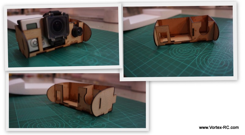
Step 6: Assemble and install the motor mount 15 mins
Use CA glue to assemble the motor mount. Ensure all notches fit as shown
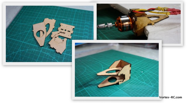
Use Epoxy to install the motor mount to the center of the Wing panel. Ensure the motor mount is straight and is centered. For Speedster PRO you will need to draw a centerline to ensure the mount is glued in straight, Also cut out the lamination before glueing so that the Epoxy adheres to the foma, and not to the tape.
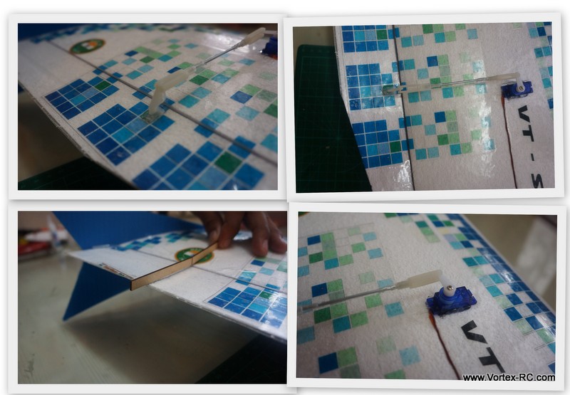
Step 7: Install servos and control linkages 25 mins
Install the servos as shown below.The servos can be installed anywhere between 30-40 cm from the panel root end. Just ensure both wing panels have the servos installed symmetrically and that they are mounted in the same direction ( Servo spline towards the leading or trailing edge ) . Glue the control horns and attach the clevis to the pushrods. Use the supplied gauge to ensure the elevons are in a slightly up-deflected position. See pictured below:
Repeat the above for the other panel
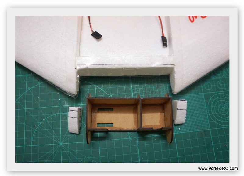
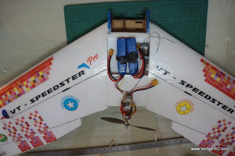
Step 8: Install motor,Rx ESC , and battery strap 15 mins
Measure and cut bays for the ESC and Receiver. The battery bay should be reinforced with some fiberglass tape, and a battery strap threaded through to the other side.

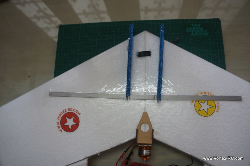
Step 9: Install winglet and skids 15 mins
Install the winglets to either side of the wing. Align as shown in pictures below. Use Hot glue to secure in place. Install the skids to either side of the leading edge. Again use Hot glue to secure in place. The skids and winglets can be made stronger by putting some hot glue on the underside. For further longevity, apply a bead of hot glue to the entire length of the skid area that will touch the ground and glue a long ziptie along the length with its locking part cut off.
Step 10. Measurement checks. 30 mins
As noted earlier Flying wings are super sensitive to CoG . Accurately measure 180 mm from the leading edge (should be the spar). With the battery installed hold the wing with two fingers to see if the wing balances. Using standard recommended gear, the CG should be close if not, then try to reposition the battery to achieve the correct CG or else use small weights to balance.
You MUST have the CG correctly before attempting to fly.
Any CG location outside 175-180mm from the panel leading edge will render this model unflyable.
Set up the radio mixing so that when:
UP elevator is given – Both Elevons move up ~2.5Cm Up
Down elevator is given – Both Elevons move down ~2.5Cm Down
Left Aileron is given: Left Elevon goes up and right goes down
Right aileron is given: Right elevon goes up and the left one goes down.
Also double check that when the control are neutral, both elevons are slightly up and match up
to the angle set by the gauge. So that the elevons move around 5 degrees UP. (1cm UP)
Note: Deflections are to be measured at the extreme tip at the trailing edge, here maximum deflection occurs.
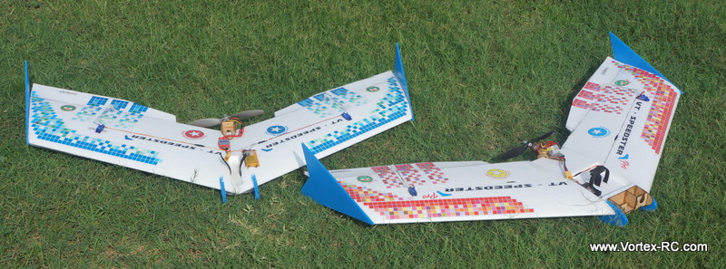
Step 11. Go out and enjoy !!
But responsibly. Find out a large open field, free from trees, buildings, obstructions and people. Ensure you comply with local regulation laws.
Before flying your model, it is recommended you have an experienced flier from your region test fly the model and trim it out for you . In case you have no such help, do not despair.
We suggest you go and do some computer simulation practice ( Realflight G4.5 , Phoenix RC etc ) afterwards this airplane should be easy enough for you to fly.
Follow all of the Preflight checks mentioned below. Double check the control surfaces. They should all be neutral and check again for control reversing. Check for wind direction. The airplane is always launched and landed against the wind. So move to a location in your field from where you have a clear area ahead against the wind to launch.
To launch the plane, watch our videos first. You should hold it on your right hand, near the leading edge just near the skids. Give it a gentle toss under half power at about 20degree angle and it should fly out. The model should go straight out on a climb. If it turns, give gentle stick commands. Reduce throttle as need to reduce the climb rate.
Always keep the model within sight and within the confines of your flying field and within visual range.
Appendix A : Field packing checklist
o Airplane
o Full charged batteries
o Radio
o Neckstrap
o Battery Tester
o Toolbox containing : Screwdriver, Allen set, Pliers, scissors, knife
o Tapes: Clear tape, FIber Tape, Double sided, paper tape
o Adhesives: CA and 5 minute epoxy
o Extra props and prop saver rubber bands
o First Aid kid ( Believe me, this is important ! )
Appendix B Preflight checklist
o All servos are secure, and linkages to servo and control surfaces are secure.
o Servo and control horns are secure and not loose.
o Servo linkages are able to move freely and are not binding on anything.
o All servo connections to the receiver, battery pack and ESC are secure and correct.
o The receiver and motor battery pack are securely fixed and cannot move during flight.
o Receiver antenna (aerial) is correctly positioned and not damaged.
o The propeller and its prop adaptor is securely mounted
o The wing, tailplane and the vertical fin are secured properly, as per the instructions
o All control surfaces move in the correct sense i.e. moving the rudder stick left moves the rudder to the left.
o All control surface hinges are secure i.e. you can’t pull the control surface away from its respective flying surface.
o The motor power works correctly, and stops when you want it to.
o Check Motor vibration
o Check CG
o Do a Range Check
o Check battery voltage
o Check for wind direction and conditions. Always launch/land against the wind.
Appendix 3 Trimming guide.
|