VT Allrounder Instructional manual V3.0
Instructional Manual
REV 3.0
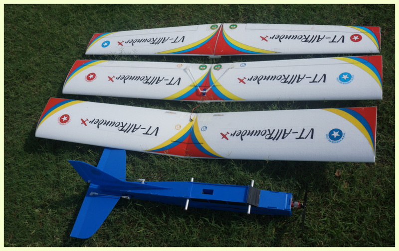
Congratulations on your purchase of the “ Vortex-RC VT-AllRounder” –
An airplane that excels as a 3 channel trainer for first time fliers, introduces ailerons to intermediate fliers and also provides a platform for fully aerobatic platform to perform any pattern maneuver in the book. A perfect Allrounder.
Please take time to read through this manual in detail as well as watch our videos that illustrate the build steps. We recommend that you read several steps ahead and test fit parts without using glue and once you double check everything then only use the adhesive. Our precision laser cutting ensures you will need minimal or no modifications to parts for a fit, and that all fits are tight and accurate. If you find any part that does not fit properly, please read the instructions and see pictures again to reorient/align correctly before using any glue.
We have written this manual so that the kit can be built individually as well as by groups of students/builders. Please follow the build in the order as written below.
Additionally we have given 2 check mark places besides each step. 
Check mark the first box when you complete the step. Check mark the second one, after you double check the step, or when doing group builds have your project coordinator inspect and check it for you.
Watch our build videos, now on Youtube.From unboxing to the maiden flight, we have it all on videos for you to see, learn and follow to ensure you get the most out of the Speedsters. Search Vortex-RC on Youtube, or follow the link : http://goo.gl/GMhxgG The manual has QR codes in each of the sections linking to relevant videos to help you easily find the videos. |
|

Contents
| What’s in the kit. | – Page 4 |
| What you need in order to complete the kit. | – Page 5 |
| Some basic stuff about materials used, and adhesives | – Page 6 |
| Build techniques – Hinging and Glueing. | – Page 8 |
| Building the Fuselage | – Page 10 |
| Building the Wing | – Page 22 |
| Installing the Electronics | – Page 34 |
| Appendix A Field packing checklist | – Page 38 |
| Appendix B – Preflight | – Page 38 |
| Appendix C – Trimming Guide | – Page 39 |
Important Measurements/Specifications:Wingspan: 1450mm
Control Throws: |
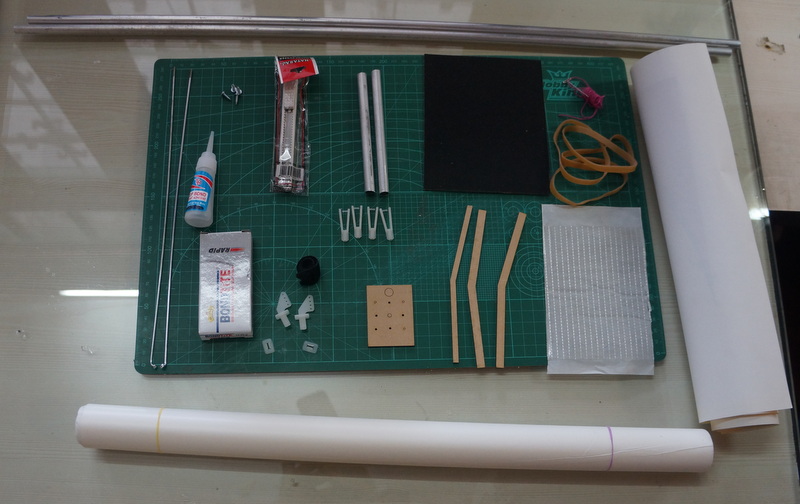
What’s in the kit.

- 1 Nos. Laser Cut Coro Sheet (A, B, C and D )
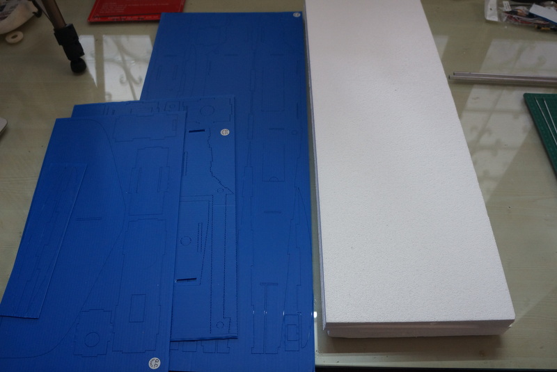
- 1 Nos. CNC cut Left Wing Airfoil Foam Panel in its wing bed
- 1 Nos. CNC cut Right Wing Airfoil Foam Panel in its wing bed
- 2 Nos CNC cut Foam wing adapters
- 2 Nos. Aluminium round spars ( For Expert Wing, 3 Pcs )
- 1 Nos. CA Adhesive
- 1 Nos. 5 minute Epoxy
- 2 Nos. Lamination sheets
- 1 Nos. Fiberglass adhesive sheet
- Control Horns ( 2 Nos. Trainer. 4 Nos. Intermediate and Expert )
- Clevis ( 4 Nos. Trainer. 8 Nos. Intermediate and Expert )
- Pushrods ( 2 Nos Trainer. 4 Nos. Intermediate and Expert )
- 4 Nos. Rubber Bands
- 3 Nos. Laser Cut Dihedral Brace
(Not included/required in Expert Wing) - 2 Nos Wooden Spar Joiner Dowels
( Only for Expert Wing ) - 1 Nos Laser Cut Motor mount
- 2 Nos. Aluminium Wing Holding rods
- 1 Nos Battery Strap
- 1 Nos Pin and thread
- 4 Nos Machine Screws
- Velcro Hook and Loop Material
- 1 Nos. 320 Grit Sand Paper
- 1 nos. Hobby Knife
- 2 Nos. Decal Sheets
|
|
Laser cut precision Coroplast parts.
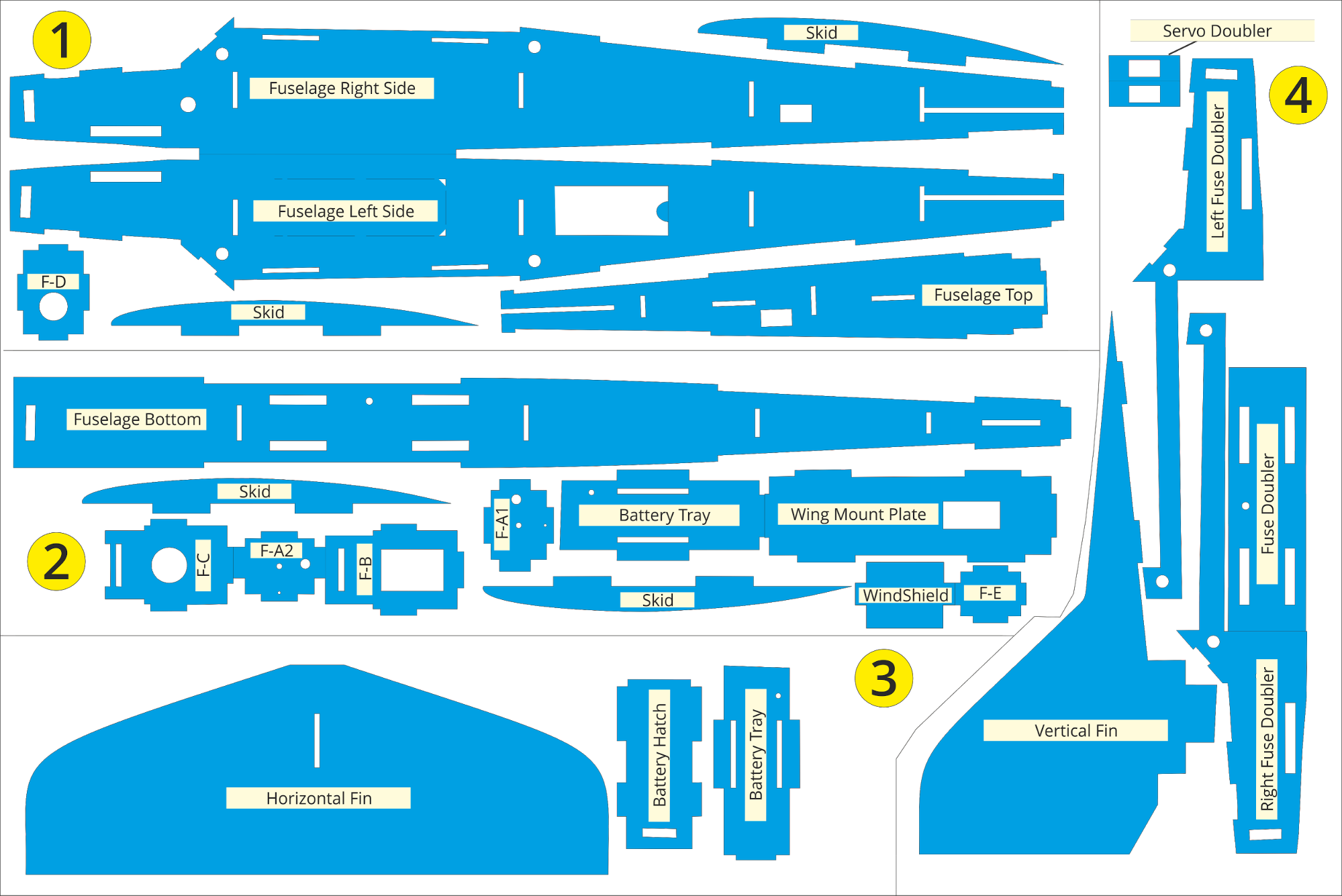
You will get all parts illustrated above but it may be oriented separately due to different sheet sizes available and packaging constraints.
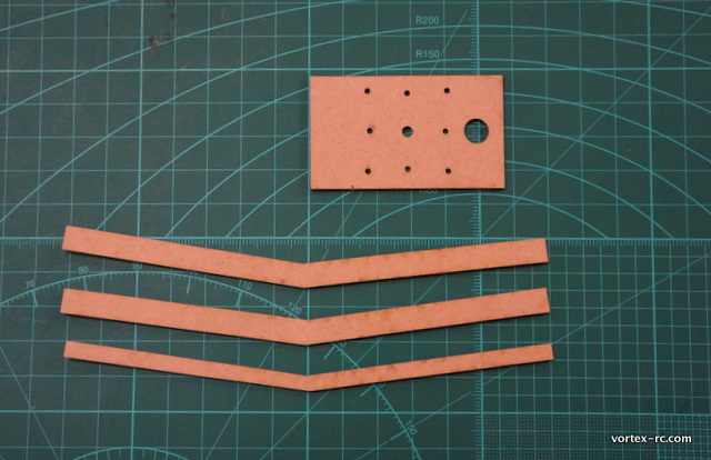
Laser Cut Plywood parts
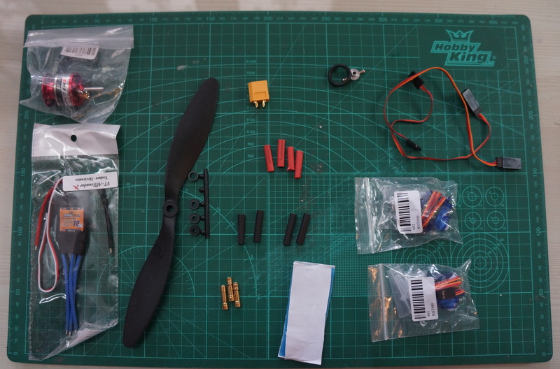
In order to complete the kit you will need the following
( check mark against each once you collect the items ) :
- Screw Driver
- Metal Ruler
- Marker Pen
- 90 deg Set Square
- Hot Glue gun and glue stick
- Clear Packing Tape
You also need a clear and a flat table/surface or floor to work with. This is very important. Having a flat surface will ensure your build goes straight and true.
You will also need the following to fly :
- 1 Nos 2200mah 3S Lithium Polymer Battery
- 1 Nos Lithium Polymer Battery Charger.
- 4 Channel or above radio set ( Tx and Rx )
About Coroplast
Coroplast, or Coro, which is a name given to Fluted PolyPropylene sheets, is a lightweight, sturdy, resilient material. Coroplast sheets has parallel flutes which make the sheets very light and strong and crushes, instead of breaking upon impact. Coro bonds extremely well with CyanoAcrylate, and epoxy. These characteristics make it suitable for RC applications.
Some building techniques and styles are unique to building RC planes using Coro and can impart even greater strength when used properly. Please read below and understand : 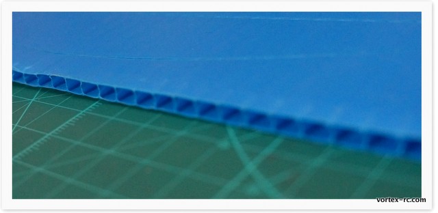
- Coro has higher strength perpendicular to the Flutes than Parallel to the flutes. Try it on a piece of scrap. Its easy to bend the material in the direction of the flutes than in the other side.
- Coro, when crushed can reduce strength. Be careful to not crush the flutes when building .
- When cutting coro, parallel to the flutes, always cut in between the flutes using a new, sharp knife/blade. When cutting perpendicular to the flutes, cut in multiple passes taking care to not crush the material.
About EPS Styrofoam
EPS, or Expanded Polystyrene , is commonly known as Thermocol and Styrofoam, is a closed cell rigid and tough foam. EPS foam is available in various densities and we use a high density EPS foam for CNC cutting our wing panels.
EPS foam is perfectly suited for hot wire CNC cutting, as it warps minimally and when cut the material is absorbed in the outer layers of the foam and does not bead, like XPS foam, which is prone to warping and beading.
EPS foam melts with CA adhesive, but Epoxy adhesives work great with it. Also, EPS foam can be strengthening by laminating it . The Hot Wire process renders a layer of ‘foam-dust’ over the panels. You need to gently sand that out before applying the lamination for best adhesion. Sanding needed is super light and should be done carefully to avoid changing the airfoil shape of the wing.
We ship the wing panels in their original wing beds. The wing beds not only provide protection during shipping, but also should be used as jigs, when laminating and sparring to reduce the chances of wing warping.
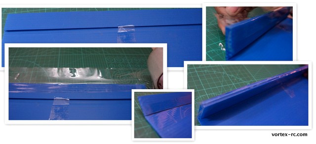
Hinging Technique.
Coro can be hinged easily. Just follow the steps below to create strong, clean and a flexible hinge joint.
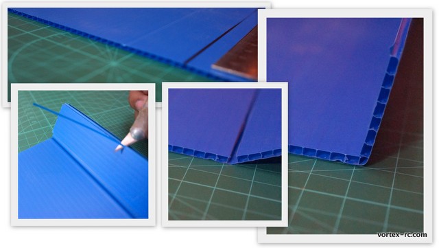
- Draw a line where the hinge has to be made, on the under side of the surface.
- Place a metal rule on the line, and adjust slightly so that the straight edge is in between the flutes and not right over them.
- Using a sharp knife carefully cut only the upper surface of the Coro. Do NOT cut all the way through. When cut, you should be able to bend the joint.
- Now we need to clear the hinge joint by removing the plastic material . Bend the joint all the way through, and tape it in place. Carefully run a sharp knife on the edge and slice of the plastic slivers on the edge.
- Once cleaned, bend the hinge joint completely, and put some packing tape on the hinge, so that half of the tape is on one side and the other half is on other side as shown below.
Glueing Technique – CA
Cyanoacrylate is a strong and fast adhesive that can bond Coro very well. However one has to be extremely careful as once bonded it can be impossible to open the joint and will damage the parts if attempted to be done. Please read below before using CA glue.
- Safety – CA can bond skin easily and instantly. Also CA fumes can irritate eyes and nose. Try to build in an open space, and use ventilation.
- Coro flutes can drip CA . Be careful when glueing coro, as excess CA will drip out.
- Use very little CA. Only a drop or so is usually needed. Building light is very important. Try to use as little glue as possible, yet ensure the joints are tight.
- There are two ways in which you can use CA :
A.Put a drop of CA on one part and then, immediately put the other part on it.
B. Hold the joint together and “flow “ the CA in place.
We prefer to Tack glue using one or two drops , and then flow a few drops through the joint.
Remember: Do NOT use CA on the Wing panels.
Build Steps:
Building the Fuselage
Build Steps:
- Cut out and label the parts
- Glue the doublers – Assemble the Battery Tray, skids, battery hatch and fuse bottom
- Prepare/Hinge the Tail surfaces
- Assemble the Fuselage
- Assemble the Wings
- Install the electronics
- Apply the decals
- Measurement checks.
- Go Fly !
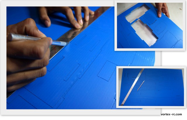
Step 1: Cut out and label the parts.  20 mins

Cut out all of the coro parts from the laser cut sheets using the knife, taking care not to damage the various notches built in. Use the metal ruler to help in scoring the straight cuts.As you take out the parts, label them by writing out the part names each as shown in the plans.
Note: We have intentionally kept the laser cut parts attached to the sheets so that small parts are not lost when we put together the kits.
Step 2. Glue the doublers – Assemble the Battery Tray, Battery Hatch, skids, Former-A and the Fuselage bottom 15 mins
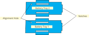
In this step, we will glue the two parts of the battery tray, two parts of Former-A and the two parts of two skids together. The battery tray has notches and alignment holes on one side. Make sure to align them properly. Also make sure the cut outs match against each other before glueing. Glue the battery tray parts together using CA adhesive .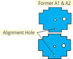
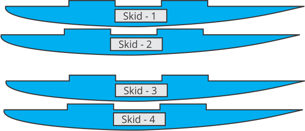
Make two skids by glueing the skid parts together. We provide 4 skids parts . The two skids are made by doubling each of the two skid parts. Use CA to glue the skid doublers. Again ensure the notches align with each other as accurately as possible. Similarly, align and orient the two parts of Former-A so that the holes, and the notches align perfectly. Then glue in place.
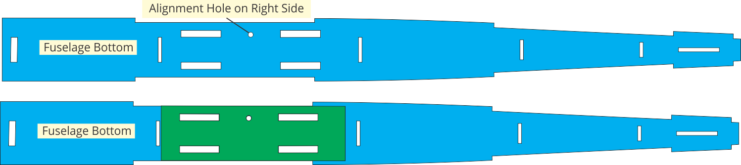
Place the Fuselage bottom sheet on the table so that the small alignment hole is on the right side. Place the Fuse bottom doubler and glue in place, making sure the notches and the cut outs align properly.
Step 3. Prepare/Hinge the Tail surfaces. 30 mins
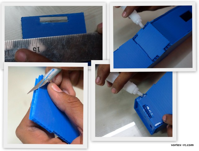
Prepare the Elevator by drawing a line 3cm from the trailing edge. You may adjust the line so it comes in between two flutes, which will enable cutting . Refer to the hinging technique explained earlier in the manual. Use the knife to cut out only one side of the coro material. The idea is to create a hinge by cutting only one side of coroplast.
Flex the joint to one side, and clear out the protruding coroplast material carefully. Add packing tape to the joint to reinforce. Test the elevator by moving it to both sides. It should be free to move.

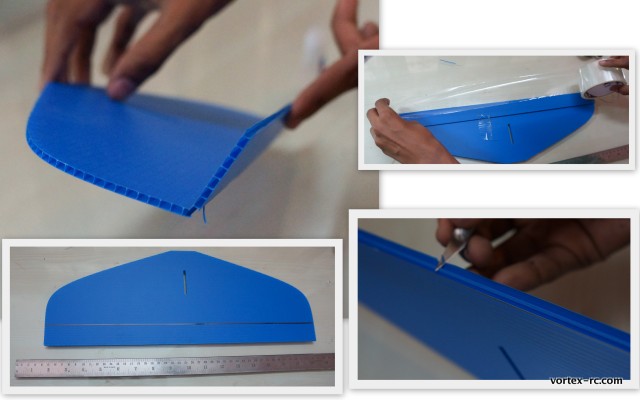
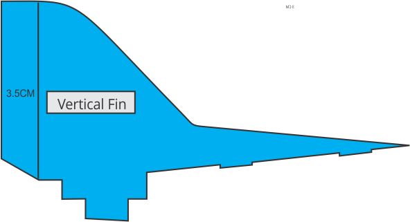
Likewise prepare the rudder by scoring a line 3.5 cm from the aft line. Follow the same technique as with the elevator to create the Rudder hinge.
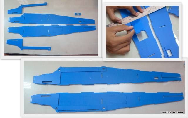
Step 4: Assemble the Fuselage 1 hour

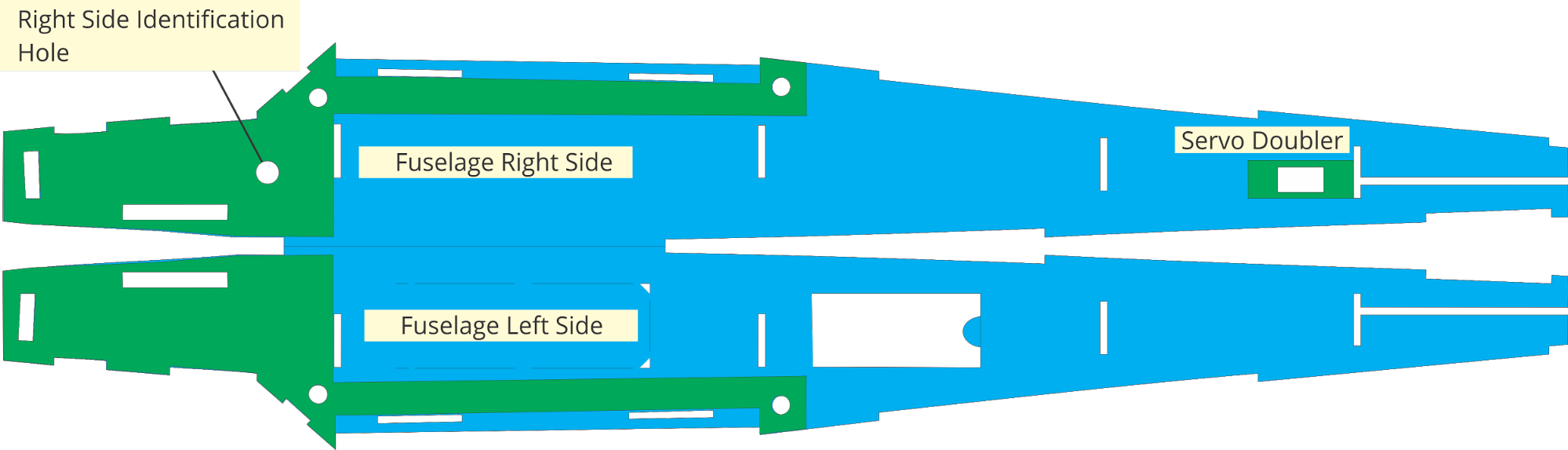
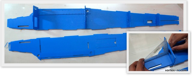
Lay out the two fuselage sides as shown below. THIS IS IMPORTANT, as there is a different left and a right side. You do NOT want to end up with 2 Left or 2 Right side fuselages. The Left side has the hatch cutout, and the right side has the servo cutout.
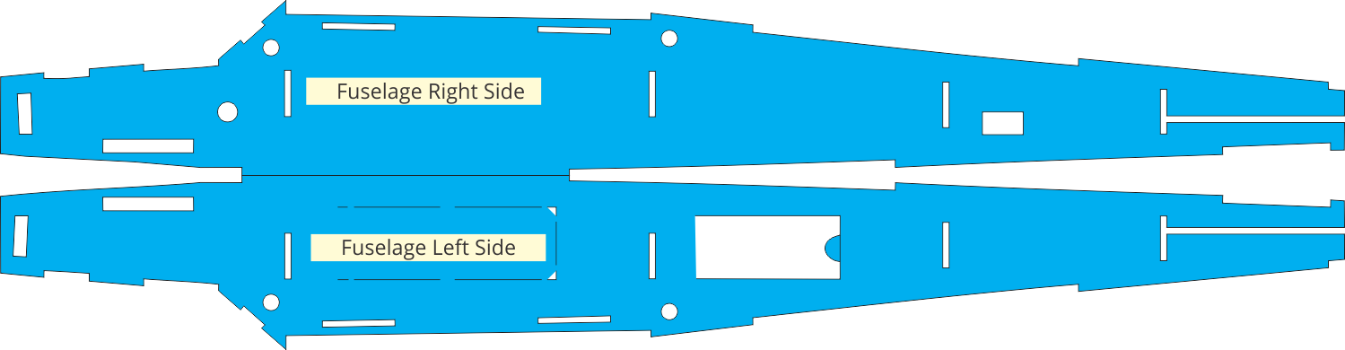
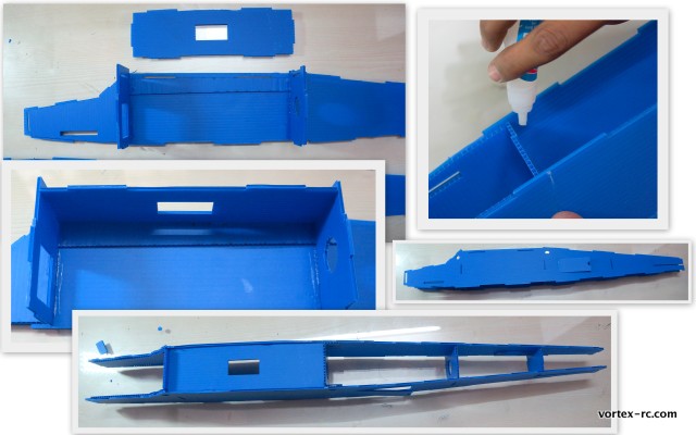
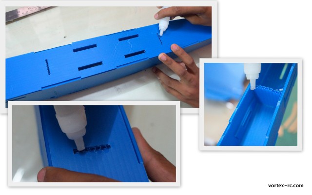
Glue the Elevator Servo Doubler and the fuselage side doublers. The Fuse side doublers must be aligned precisely with the notches, and the cutouts.There is a different Left and Right Fuse doubler. The Right Fuse doubler has a hole. Double check before adding glue. The Servo doubler needs to be glued accurately too.
Lay out the Formers A,B,C,D and E as illustrated below. Each former has a top and a bottom side. Be sure to align them properly as shown below. 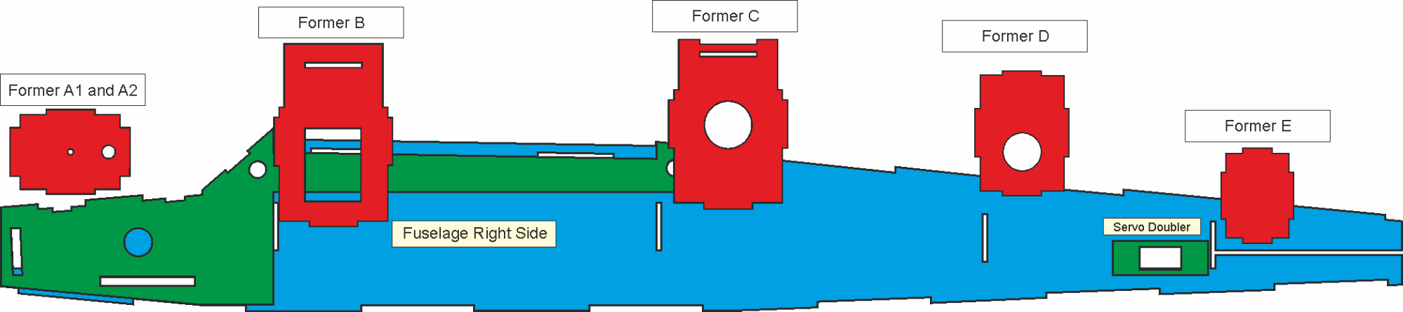
Using a set square to maintain 90 degrees. Glue in the Formers B,C,D and E to the Right fuse section. Note : Former A is NOT glued at this stage. Also note that each Former has a different top and bottom sides. Take care to NOT glue the formers upside down and ensure the notches align perfectly.

Next, Take the Wing mount plate, and align it correctly. Test fit it into the notches within the fuse, and the Former B and C . Take time to fit it as accurately as possible. The Wing mount plate fits only from one side. So be sure to align properly. Add CA to secure the plate in position
The Wing Mount plate has to be oriented so the cut out is on the rear side.
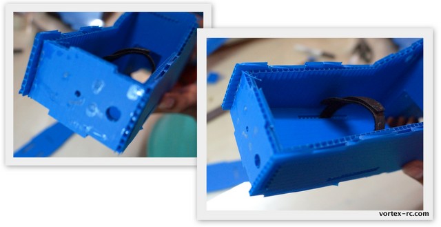
Carefully lay the LEFT side of the fuselage over the formers and the wing mount plate. Take time to accurately fit each of the notches in place, without crushing or damaging the coro. Once satisfied, flow a few drops of CA in place to ONLY the joints in Former B, C and the Wing mounting plate.
Doesn’t it looks more like a plane now ?
Place the fuselage over the flat building table to ensure it is straight, and then flow a drop of CA to the joints of the formers C,D and E.
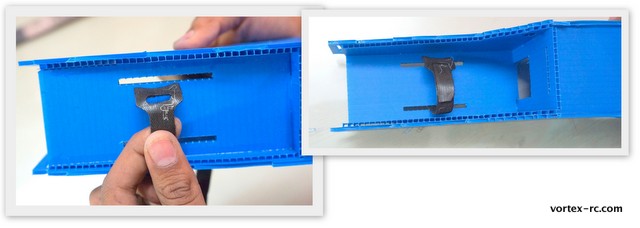
Put the battery strap through the hole in the battery tray. Make sure you put this in the right way . Glue the battery tray into the right Fuselage section. Note that the notch goes towards the back.
Install the Former A in place. Carefully align the notches and fit it in place. The Alignment hole goes towards the bottom.
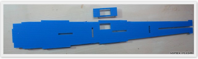
Install the fuselage base. Put the fuselage section top down, and align the notches in the fuselage base with those of the formers and the fuse sides. The FUselage bottom should be installed such that the FUse doubler is on the inside. Again inspect and carefully fit each joint and ensure the Coro is not crushed or damaged . Once satisfied, add CA glue to each joint.

Hinge the Battery hatch and Install the battery hatch and windshield.
Create a hinge on the Battery hatch, by following the hinging technique explained above. The battery hatch has to be prepared by scoring a line 2cm from the front.
Test fit the battery hatch and windshield.
Note: Glue ONLY the front part of the hatch the rear part is left to open. Glue the windshield piece securely.
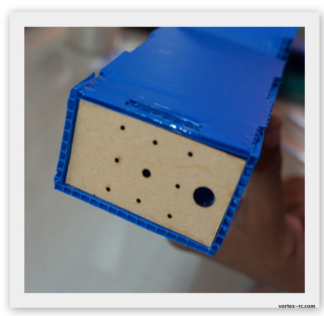
Glue the Laser cut ply motor mount .
Be sure to align the holes accurately and glue in place .
Prepare the Fuselage top by glueing in the Servo doubler in place. Place the Fuse top as shown below and glue in the doubler in place. The Servo cutout is on the LEFT side of the fuselage, but the doubler is glued to the inside surface, so when you glue in the cutout should be on the right side as shown below.

Align the Fuselage top with all of the formers and Fuse sides carefully. Be sure the coro is not crushed or damaged and that each notch fits properly. When satisfied, flow a few drops of CA over each joint. Hold in place to ensure a good, tight bond is made.
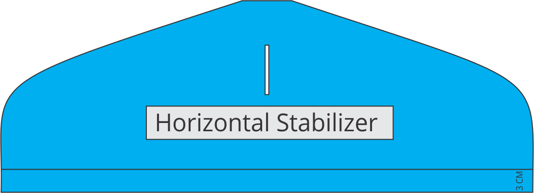
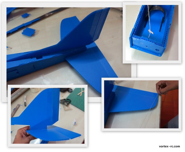
Install the stabilizer . It is very important to glue in the Horizontal and Vertical stabilizers square and true. Take your time to align these parts properly before adding glue.

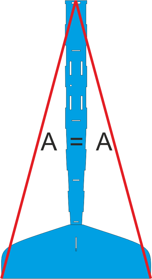
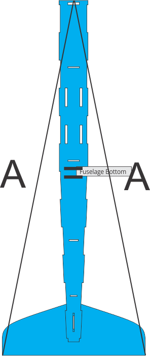
Use the Supplied Pin and thread to ensure that the Stabiliser is perfectly centered as shown below.
Without using any glue, slide the rudder through the notch in the stabilizer. and carefully install the stabilizer in place. The notches help align the parts accurately, and the rudder goes all the way through the stabilizer down to the base of the fuselage. You also need to measure the distance from the nose, to the tip of the stabilizer using the pin and thread to make sure the distances are equal. Adjust till satisfied, and then without moving anything, add glue and give it a few minutes to bond securely.
Install the skids as shown below. Flow CA glue through the joints to ensure these are properly glued in.
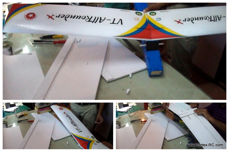
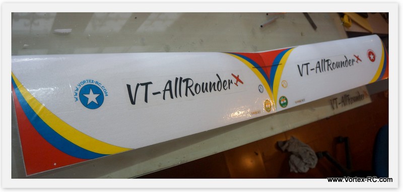
Apply the Fuselage Decals.
From the supplied Decal sheet, cut out the Left and the right Window sets and also the square black Windshield. 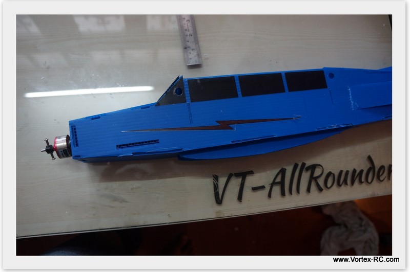
Carefully peel off from the backing and align and glue in place as shown.
After glueing, carefully cut off the holes in the decals where the wing mount rods will be installed.
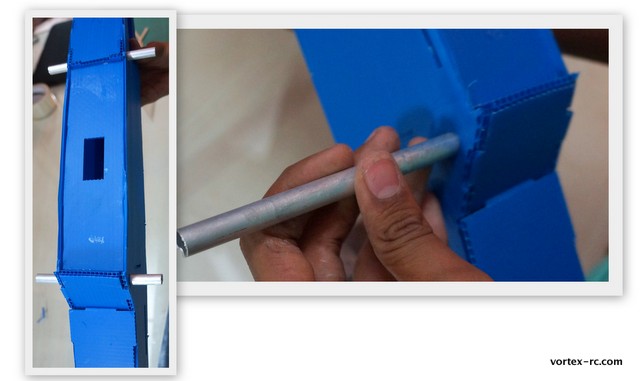
Install the wing mounting rods
Congrats. This completes your fuselage. Hope you have enjoyed the build so far. Take a short coffee break and we shall then get back to glue the wings together !
Instructions for building the Wing
|
The Trainer, Intermediate and the Expert wings are built similarly. Except the following differences : – Intermediate wing requires installing the servo in the center, after the wing build is completed. – Expert wing requires installing 2 servos and the necessary Control Linkages The build process below is for all the three wing types. Most of the steps are common, but pay attention to measurements, and specially the wing joining steps. |
We shall illustrate the steps for building the Right wing. Follow Step 5 for Left wing also.
Step 5. Laminate the Wing panels. 1 hour

Note : In order to build the wings straight and true. Please follow the instructions below carefully. The airfoils are high performance and in order to use them effectively, you need to ensure the wing is not warped or twisted. It is very easy to warp the wings if the instructions below are not followed.
|
NOTE: We have figured out, that it may be better to put in the decals, before the Lamination is done. This way, the longevity of the decals is increased. So just follow the steps below, but after sanding, install the decals first, and then laminate. |
Build on a Flat table or surface
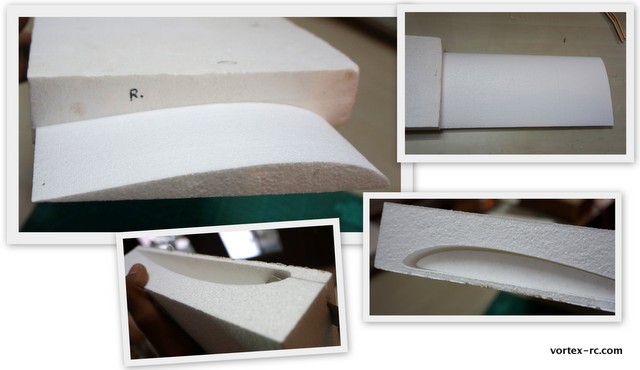
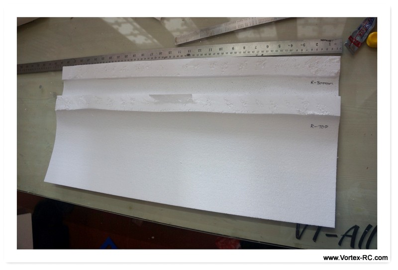
A Take out the wing cores from their beds carefully. Note that there is a Left wing and a right wing. How do you identify ? There should be a R and a L written on the wing bed. Also, the root edges of the Trainer and Intermediate wings are cut at an angle ( to give the necessary dihedral ). Each wing panel has its own bed. Do NOT mix this up. Label the wings and beds using a marker pen . You should have Wing-L , Wing-R, Bed-L and Bed-R at the end of this step.
B. Take out the wings from the its bed and cut the wing bed from the top to make a top and a bottom side . Label them again. So you make a Bed-R Top and Bed-R Bottom.
C. Lightly sand the wings before laminating to get a better adhesion. Very gently and uniformly sand using the supplied sandpaper keeping the wing panel on its bed. . Idea is to just remove the thin outer brittle layer of foam . After sanding, clean up the wing with a cloth.
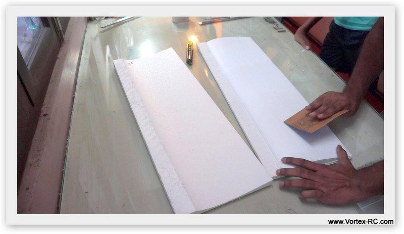
D. Laminate the wing using the supplied sheet of lamination roll. You may need some help (another pair of hands ) to do this cleanly.
-Place the wing on the Bottom wing bed, and start laminating from the trailing edge.
-Keep about 10mm extra on the trailing edge.
-Peel off the backing and lay down the lamination. Try to avoid forming any wrinkles. and as you move towards the leading edge, press the lamination roll firmly onto the wing. 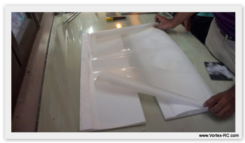
When you reach the leading edge, turn the wing panel upside down, and place it over the Top wing bed. Continue laminating till you reach the trailing edge. At this point you can remove the Wing panel from the bed, and trim off the excess material.
E. Install the spar (Only for the Trainer and Intermediate Wings. The Expert Wing Spar is installed later). Keep the wing panel upside down on its corresponding bed. Ensure the bed is on a flat surface and the wing sits in snugly.
Carefully and gently install the aluminium round spar. You may need to trim the ends of the aluminium spar. Once satisfied, Mix some epoxy, and apply evenly across the length of the spar and gently install in place. Make sure you lay the wing on its bed to avoid warping.
Build the Ailerons
|
Aileron Measurements: For Intermediate Wing: 10cm from root. 5 Cm From Tip. Aileron width 4 Cm Mark out the ailerons as per the above measurements and cut out using a sharp knife. You may need to use multiple passes to cut, but be sure to cut cleanly. Also before cutting double check measurements and also ensure both ailerons are symmetrical.
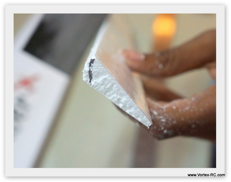
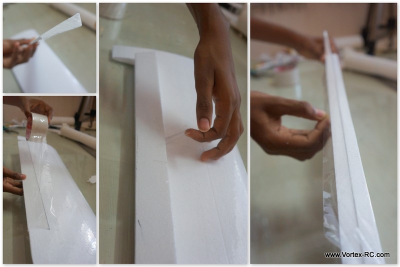
The next step is to bevel the ailerons. Mark a 45 degree line from the top of the aileron on the side as shown. The idea is to bevel the bottom side so that the hinge line will be created on the top edge. Put the aileron back side up draw a line, parallel to the length of the aileron about 1 CM behind the leading edge. Carefully cut out the lamination material from this line. Sand carefully so that the bevel is created uniformly across the length of the aileron.
For Hinging, Follow these 4 steps to create a slop free, tight and reliable hinge joint: A. Use 3 small pieces of tape to hold the aileron tightly in place and fully deflected in Down position. Make sure the top line is aligned properly B. WHile keeping the aileron deflected apply a length of clear tape along the joint.
C. Flip the Aileron the other side, and tape in place using a small piece. |


F. Join the panels
|
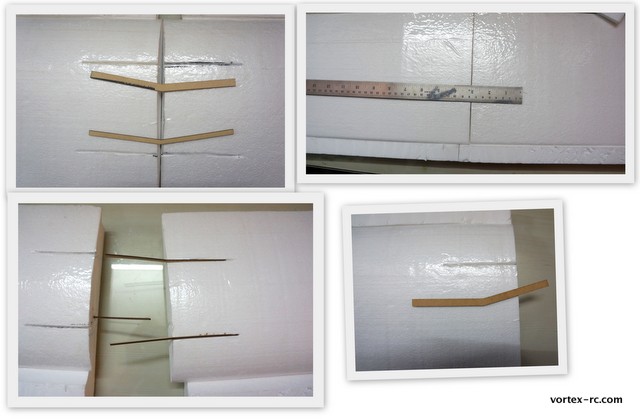
For Intermediate/Trainer Wings : use the Laser Cut dihedral brace. |
|
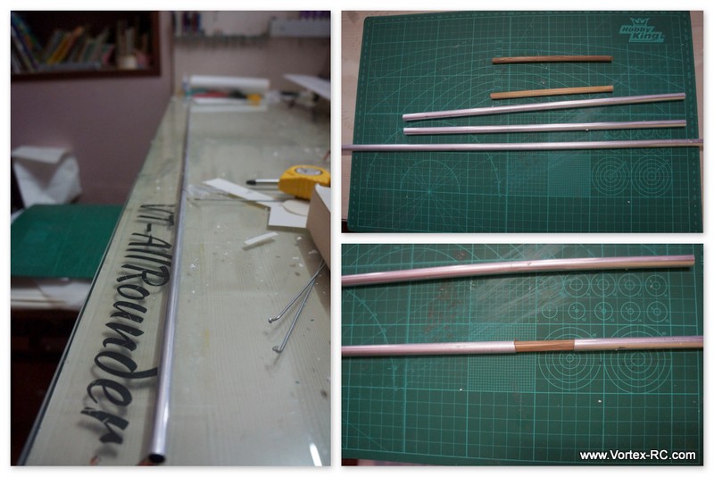
For Expert Wing: We shall create a single spar by joining the two smaller aluminum rods at each end of the longer aluminum rod. So the configuration would be such : After the Spar created, test fit the spar in place and make sure the wing roots mate evenly at the center joint. If not, then lightly sand. Once satisfied liberally, mix up some epoxy , and coat the entire length of the spar, and also the wing root, and install/glue in place. Leave the wing aside to cure.
|

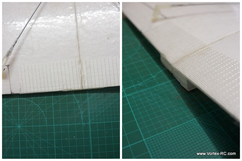
Double check everything. and leave the wing to cure. Once cured, apply some clear packing tape over the entire center joint, and also on the braces. You can also put the fiberglass tape near the root joint on the trailing edge as shown below, The Fiberglass tape prevents the trailing edge to be crushed when rubber bands are mounted.:
|
Installing the aileron servo For Intermediate Wing :
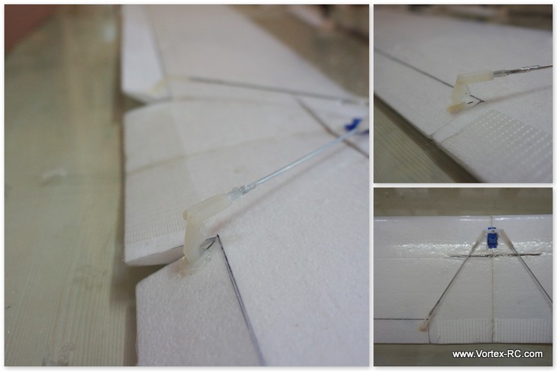
The Intermediate wing uses a single servo located in the center of the wing panel on top of the wing. The servo cut out should be created ahead of the spar and the two pushrods are angled towards each of the ailerons. You will need to make sure the Control horns are installed angled inwards to line up in a straight line with the controlrod >
|

|
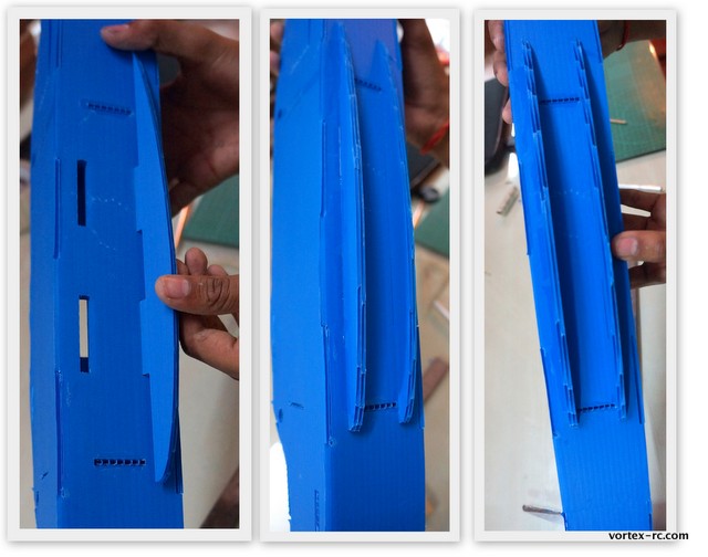
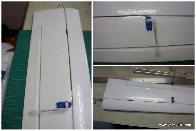
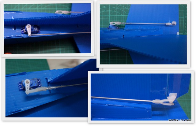
Installing the aileron servo For Expert Wing : The expert wing requires a servo to be installed on each wing panel on the underside of the wing. The servo should be installed about 40 cm from the root . Servo extensions should be used to extend the wires out, and the servo wire can routed in the groove pre-cut for the spar. See pictures below and install the Control horn, and linkages. |
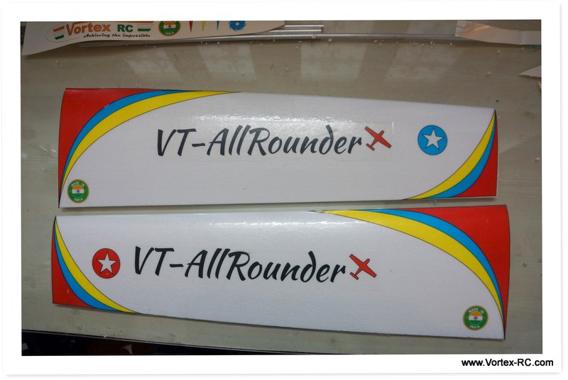
G. Put the decals and Install the wing adapter base.
Cut the supplied decals and put them as shown here.
The last step here is to glue the foam wing base adaptors. The two adaptors should be glued to the wing root section as shown below. The wing adaptors make a perfect seat for the wing, and are cut precisely to give the correct dihedral angle and support to the wings. Make sure the thin sides of the adaptor face towards each other. You may need to trim the leading/trailing edges of the adaptors slightly to fit the wing on the fuselage.
Whew ! Congrats your wing is now ready. Just a few more checks and we should be ready to hit the field !

Installing Electronics
Step 6 Install the electronics 30 mins
Center the Servos and Install the Servo Arms.
Using the RC Tx/RX, connect the servos to the Elevator/Aileron Channel and ensure the Trims are set to Neutral. This should center the servo. At this position install the Servo Arm, so that the arm is perfectly perpendicular to the servo. Unplug the servo from the receiver and put the screw in place.
Glue the Servos in Place
The servo cutouts are designed to accommodate standard 9gm servos. We have kept the cout outs a little small to allow for size variation amongst different brands. Adjust the cut out using a knife for a snug fit.When satisfied thread the servo wires through the holes in the formers and glue in place using little hot glue.
Tip: Wrap the servos in some packing tape before glueing to make later removal easier.
Install the Control Horns.
Install the Control Horns on the Elevator and the Rudder in the locations as shown below. The Control horn location should be such that they are in straight line with the servo arm. 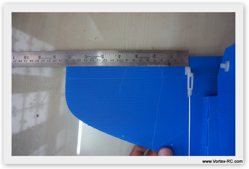
Prepare the Control Rods.
You need to cut the supplied control rods to the correct lengths. Install the clevis on one end of the control rod using some hot glue. Keeping the servo centered install it in the second outermost hole. Now cut the rod about 2 Cm short of the control horn, and while keeping the control surface neutral, glue the other clevis also.
Install the Motor/ESC and the Prop.
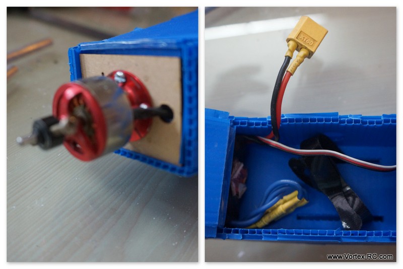
Step 8. Measurement checks. 30 mins
Double check the following and adjust as needed.
1> Stabilizer A=A from Nose. Use the Pin and thread to check this
2> Wing tip B=B from Nose
3> Wing and stab parallel. Eyeball the wing and the stab from behind the tail to check if the tail stabilizer is parallel with the wing. If not, then put a couple of layers of paper tape to one side of the wing foam adaptor. This is very important
4> CG Check. CG should be at the spar position Which is approximately 65mm from the leading edge of the wing (at root ). This is very important
5> Lateral balance check
5> Control Surface checks : Check that all surfaces are neutral. All surfaces move in the correct directions and are not reversed and that there is adequate throws.
This is very important
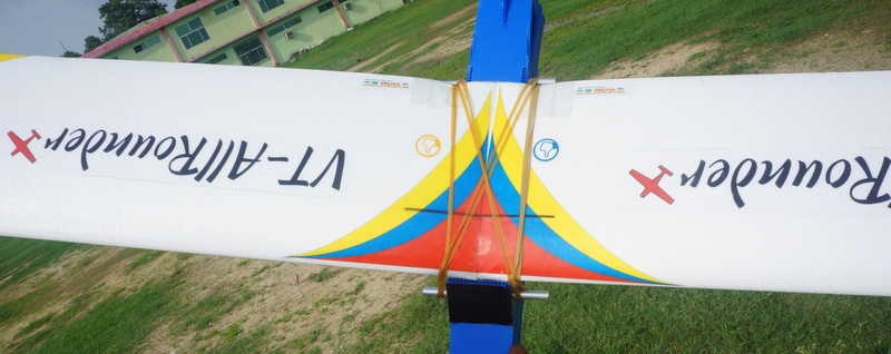
The wing is held down by the supplied 4 rubber bands. Install two rubber bands straight, ie parallel to the fuse and the two rubber bands criss-cross, so that they lock down the first two bands. Make sure your wing trailing edges have the fiberglass tape, to avoid damage. The battery should be installed in the front and strapped down tight. Adjust the placement of battery to get the CG correct. Make sure the battery is securely fastened.
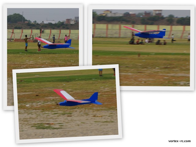
Step 9 . Go out and enjoy !!
But responsibly. Find out a large open field, free from trees, buildings, obstructions and people. Ensure you comply with local regulation laws.
Before flying your model, it is recommended you have an experienced flier from your region test fly the model and trim it out for you . In case you have no such help, do not despair.
We suggest you go and do some computer simulation practice ( Realflight G4.5 , Phoenix etc ) afterwards this airplane should be easy enough for you to fly.
Follow all of the Preflight checks mentioned below. Double check the control surfaces. They should all be neutral and check again for control reversing. Check for wind direction. The airplane is always launched and landed against the wind. So move to a location in your field from where you have a clear area ahead against the wind to launch.
To launch the plane, hold it under the wings ( near the CG ), give full power and gently toss it in a 15 degree upwards angle. The model should go straight out on a climb. If it turns, give gentle stick commands. Reduce throttle as need to reduce the climb rate.
Always keep the model within sight and within the confines of your flying field.
Appendix A : Field packing checklist
- Fuselage
- Wings
- Fully charged batteries
- Radio
- Neck Strap
- Battery Tester
- Toolbox containing : Screwdriver, Allen set, Pliers, scissors, knife
- Tapes: Clear tape, FIber Tape, Double sided, paper tape
- Adhesives: CA and 5 minute epoxy
- Extra props and prop saver rubber bands
- First Aid kit – Believe me this is important.
Appendix B Preflight checklist
- All servos are secure, and linkages to servo and control surfaces are secure.
- Servo and control horns are secure and not loose.
- Servo linkages are able to move freely and are not binding on anything.
- All servo connections to the receiver, battery pack and ESC are secure and correct.
- The receiver and motor battery pack are securely fixed and cannot move during flight.
- Receiver antenna (aerial) is correctly positioned and not damaged.
- The propeller and its prop adaptor is securely mounted
- The wing, tailplane and the vertical fin are secured properly, as per the instructions
- All control surfaces move in the correct sense i.e. moving the rudder stick left moves the rudder to the left.
- All control surface hinges are secure i.e. you can’t pull the control surface away from its respective flying surface.
- The motor power works correctly, and stops when you want it to.
- Check Motor vibration
- Check CG
- Do a Range Check
- Check battery voltage
- Check for wind direction and conditions.
Appendix 3 Trimming guide.
- Trim in calm conditions.
- Make multiple tests before making adjustments.
- If changes are made, go over previous steps and verify or readjust as necessary.
|
To Test For |
Test Procedure |
Observations |
Adjustment |
|
1. Control neutrals |
Fly model straight and level |
Adjust the transmitter trims for hands off straight and level flight |
Adjust clevises to center transmitter trims |
|
2. Control throws |
Fly model and apply full deflection of each control in turn |
Check the response of each control |
*Aileron Hi-rate: 3 rolls in 4 seconds. *Lo-rate: 3 rolls in 6 seconds. *Elevator Hi-rate: to give smooth square corner. *Lo-rate: to give a loop of approx. 130′ dia.. *Rudder Hi-rate: approx. 30-35 degrees for stall turns. *Lo-rate to maintain knife edge flight. |
|
3. Decalage |
Power off vertical dive. Release controls when model is vertical (elevator must be neutral). |
A. Does the model continue straight down? B. Does the model start to pull out (nose up) ? C. Does the model start to tuck in (nose down)? |
A. No adjustment B. Reduce incidence C. Increase incidence |
|
4. Center of gravity |
Method 1: Roll model into near vertically banked turn. Method 2: Roll model inverted. |
A. Nose drops B. Tail drops C. Lots of down elevator required to maintain level flight D. No down elevator required to maintain level flight, or model climbs |
A. Add weight to tail B. Add weight to nose C. Add weight to tail D. Add weight to nose |
|
5. Tip Weight (course adjustment) |
Fly model straight and level upright. Check that aileron trim maintains wings level. Roll model inverted, wings level. Release aileron stick |
A. Model does not drop a wing B. Left wing drops C. Right wing drops |
A. No adjustment required B. Add weight to right tip C. Add weight to left tip |
|
6. Side Thrust |
Fly model away from you into any wind. Pull it into a vertical climb (watch for deviations as it slows down). |
A. Model continues straight up B. Model veers left C. Model veers right |
A. No adjustment needed B. Add right thrust C. Reduce right thrust (move thrust line left) |
|
7. Up/Down Thrust |
Fly model on a normal path into any wind. Parallel to strip, at a distance of around 100m from you (elevator trim should be neutral as per test No.3). Pull into a vertical climb & neutralize elevator. |
A. Model continues straight up B. Model pitches up (goes towards top of model) C. Model pitches down (goes towards bottom of model) |
A. No adjustment needed B. Add down thrust C. Reduce down thrust |
|
8. Tip Weight (fine adjustment) |
Method 1: Fly model as per test No.6 and pull it into a reasonably small dia. inside loop (1 loop only). Method 2: Fly the model as per test No.6 and push it down into an outside loop (1 loop only & fairly tight). |
A. Model comes out with wings level B. Model comes out right wing low C. Model comes out left wing low |
A. No adjustment needed B. Add weight to left tip C. Add weight to right tip |
|
9.(a) Aileron Differential Method 1: |
Fly the model towards you, before it reaches you, pull it up into a vertical climb. Neutralize controls, then half roll the model |
A. No heading changes B. Heading change opposite to direction of roll commands (ie. heading veers to models & your left after right roll). C. Heading changes in direction of roll command |
A. Differential OK B. Increase differential C. Reduce differential |
|
9.(b) Aileron Differential Method 2: |
Fly the model on a normal pass and do 3 or more rolls |
A. Roll axis on model center line B. Roll axis off to same side as roll command (ie. right roll, roll axis off right wing tip) C. Roll axis off to opposite side of model as roll command |
A. Differential OK B. Increase differential C. Reduce differential |
|
10. Dihedral |
Fly model on normal pass and roll into knife-edge flight, maintain altitude with top rudder (do this test in both left & right knife-edge flight) |
A. Model has no tendency to roll out of knife-edge flight B. Model rolls in direction of applied rudder C. Model rolls in opposite direction in both tests |
A. Dihedral OK B. Reduce dihedral C. Increase dihedral |
|
11. Elevator alignment (for models with independent elevator halves) |
Fly model as in test #6 and pull it up into an inside loop. Roll inverted and repeat the above by pushing it up into an outside loop |
A. No rolling tendency when elevator applied B. Model rolls in same direction in both tests C. Model rolls in opposite direction in both tests |
A. Elevators are in correct alignment B. Elevator halves misaligned. Either raise one half or lower the other half C. One elevator half has more throw than the other (model rolls to the side with the most throw). Reduce throw on one side or increase throw on the other |
|
12. Pitching in knife-edge flight |
Fly model as per test no. 10 |
A. There is no pitching up or down B. The nose pitches up (the model climbs laterally) C. Nose pitches down (model dives laterally) |
A. No adjustment needed B. Alternate cures: 1. Move the CG aft 2. Increase wing incidence 3. Add down trim to ailerons C. Reverse the above |